Ignition System Topics
If you’re having a hard time diagnosing a misfiring Ford, the task will be made a lot easier with the aid of a Snap-on lab scope and scan tool.
The software in the scope contains a specific test just for Ford vehicles and testing their coils – it’s called the Coil Current RFI Test. This article shows you how to get your scope and vehicle set up in order to run the test and get your results.
The software in the scope contains a specific test just for Ford vehicles and testing their coils – it’s called the Coil Current RFI Test.
This article shows you how to get your scope and vehicle set up in order to run the test and get your results.
The test you need is in the Guided Component Tests section. Go to that, then Fuel Injection System, choose Ignition Tests, followed by Secondary Tests, and then select the Coil Current RFI Test option.
You will be advised to set the amp probe up at the 20 am setting then hook it around the coil on the battery’s positive side.
From there, pull the coil out, check it over to make sure that it’s not sparking on anything, then on your scan tool hit View Meter.
Start the car to generate a pattern on the meter, and if you need to you can also zoom out on the screen for a wider view.
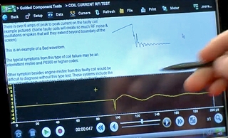
Once the pattern is shown, you can scroll up in the background and take a look at an example of a good pattern before comparing it against what you are getting from your vehicle.
If you then go down a little further you will get an example of a bad pattern, which will show you instances of RFI spikes and bad noise.
If there are no spikes or noise artefacts in your pattern then this would indicate a good coil in the vehicle you’re working on.
There are many different ways to diagnose ignition problems on a vehicle using a Snap-on® lab scope.
You might be facing a faulty ignition coil or something similar but you’re having a difficult time trying to get to the bottom of things.
One way to work your way to a solution is to run what’s called a Coil Current Ramp Test, which operates with the aid of the diagnostic software on Snap-on platforms.
With your low amps probe hooked up around one of the wires on the vehicle’s number one coil, in your lab scope settings make sure you’re on a 10 amp scale and a 10 millisecond sweep.
Once you’re recording, start the vehicle and generate some data for a few seconds before pausing the recording and switching off the vehicle.
For this example we’re working on a 2013 Ford Fusion as it uses what’s called a multi-strike ignition, which is trying to dissipate all of the extra energy in the coil by firing multiple times.
Doing this also helps the fuel burn more efficiently when the vehicle is idle. Some BMW models use four or five multiple strikes just to dispel the energy.
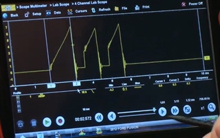
Back on the lab scope, turn on your cursors and take a better look at the timing of the pattern.
Measure the first strike, because that’s the one you should be most concerned about. In this example we got 1.32 milliseconds, which is well within a good average of one and a half milliseconds.
You want to make sure that the current ramp is nice and smooth. If it ramped up very quickly then you would have an issue with a high current flowing through that coil driver.
And it’s important to make sure that the pattern is straight – anything with a curve would show another issue with the coil.
This is a pretty simple and unobtrusive test you can run to make your life easier when it comes to ignition coil diagnosis.
Did you know that fuel injectors on Direct Injection vehicles work differently than a standard fuel injector?
A lot of newer cars use petrol direct injection. It's a far more efficient way of injecting fuel into the engine.
Manufacturers had been using this system on diesel vehicles for quite some time so if you've never worked on a diesel you might not know it's a little bit different.
With a Snap-on scan tool hooked up to the vehicle, we can see how the data looks on a lab scope and how the pattern is actually different than a standard fuel injector.
Inside all of the Snap-on scope tools is the Guided Component Tests section, which gives us a lot of information on how things work and where to connect the tool to the vehicle – let’s use a 2016 Ford Escape with an EcoBoost® motor for this example.
With the vehicle identified, go into the Fuel Injection System menu and then into Fuel System, followed finally by Fuel Injector.
Now the tool going to give us some information so we'll go into Component Information and it tells you how the system operates:
The gasoline direct fuel injector delivers fuel directly into the cylinder under high pressure.
Each injector is controlled by two circuits from the PCM
A boosted voltage supply up to 65 volts is generated in the PCM and used to initially open the injector
The injector driver controls three transistors switches that apply the boost voltage to open the injector and then modulates the current to hold the injector open
If boost voltage is unavailable, the correct injector opening current might not be generated in the time required
The PCM contains a smart driver that actually monitors each side to see whether there's a problem and it will display a code for whatever the problem happens to be
The tool tells you that the best place to test on these vehicles is either at the injector itself, which can be hard to reach, or a 16-pin connector on the left rear side of the engine, above the engine oil filter housing. That’s where the connection is made for this example.
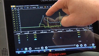
If you go into your lab scope you can see two different patterns displayed, one after the other.
The second pattern is powering up the fuel injector and contains a small voltage spike at the same time as the amperage goes up.


